
Industrial Smart Digital HiQDT Conductivity Sensors to Directly Interface to ANY RS-485 MODBUS RTU Controller
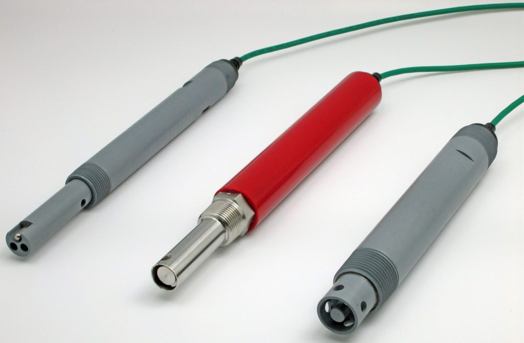
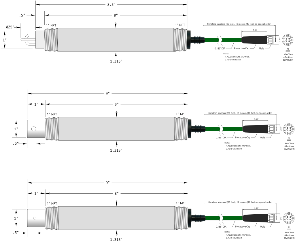
The AST52, AST41 and AST50 sensors shown to left in standard configuration without waterproofing option installed. Sensors are available for all possible installation types including inline, immersion, submersible, sanitary and HOT-TAP valve retractable schemes.
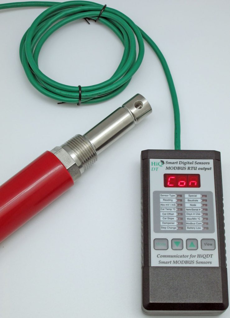
Shown below is handheld communicator (HHC) automatically detecting that a conductivity sensor has been connected.
Electrical Conductivity (EC) Units Measured
- microSiemens/cm (μS/cm) or
- milliSiemens/cm (mS/cm)
Conductivity Units Computed
- Salinity (PSU)
- Total Dissolved Solids (TDS) in ppm
- NaCl, KCl and TDS 442
- MegaOhms (MΩ)
- Both linear or special ultrapure water (UPW) non-linear automatic temperature compensation (ATC) are available
Other Available Measurements with HiQDT Sensors
- pH & ORP
- Dissolved Oxygen (D.O.)
- Ion Selective (ISE)
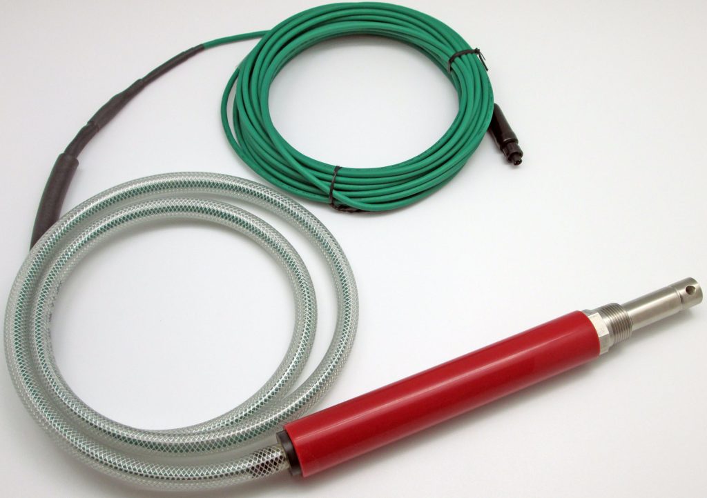
Shown to left is AST41 sensor with WPIT sealing and braid-reinforced sealing hose factory installed to make sensor suitable for use in outdoor installations with moisture, rain as well as washdowns.
Alternate waterproofing sealing options are available for fully submersible use even when an immersion rod or standpipe is not used for installation.
Smart MODBUS Conductivity Sensors with Integral Calibration, Intelligent Analytics, Predictive Maintenance for Plug & Plug Hot-Swap Operation in Continuous Field Measurements
INSTALLATION STYLES:
- Inline
- Immersion
- Submersible
- Sanitary
- HOT-TAP Valve Retractable
- Special installation styles are available upon request as special order configurations (inquire to factory)
CELL CONSTANTS
- Anywhere from K=0.01/cm up to K=20.0/cm
MEASURING RANGES
- Down to Ultrapure Water ( 0-2 μS/cm | 0-18.2 MΩ)
- Up to 2,000,000 μS/cm ( 2,000 mS/cm )
- Computed Salinity up to 50.000 PSU
- Computed Total Dissolved Solids (TDS) to 100,000 ppm
- Computed Resistivity in MΩ with UPW ATC curve
OPERATING MODES:
- Standard Range & High Range Modes
- Can toggle between standard and high range mode while sensor is in use as most appropriate for sample for best resolution and scaling
- Ultralow Range Mode
- With special UPW temperature compensation
UNIQUE FEATURES
- Sensors are supplied precalibrated with certificate ready for immediate field commissioning upon arrival
- Auto configuration of cell constant & range mode for controllers supplied with smart conductivity sensors
- Time since calibration last performed can be used for predictive maintenance to ensure accurate field readings
- Separate span gain calibrations for standard & high range modes for best reading in any operating mode
MATERIALS OF CONSTRUCTION
- Electrodes:
- 316SS, Titanium, Hastelloy C-276, Monel
- Insulators:
- CPVC, TEFLON (PTFE), KYNAR (PVDF), PEEK
- “O”-Rings:
- EPDM & EPR, VITON, AFLAS, KALREZ
- Compression Fittings:
- 316SS, KYNAR (PVDF), PolyPropylene (PP)
SPECIFICATIONS
- Up to 500 psig
- Up to 205 ℃ for Inline, Sanitary & HOT-TAP Use
- Up to 85 ℃ for Submersible Installations
- Process Connections:
- Inline from ½”MNPT up to 1”MNPT
- Sanitary from ¾” to 2½” TRI-CLOVER Flange
CLICK HERE for complete webpage on SMART DIGITAL HiQDT MODBUS RTU MEASUREMENT SYSTEM for core information that is shared for all measurement types and details on the ASTI supplied PLC & HMI packages for turn-ready commissioning. See installation guide for additional details & information.
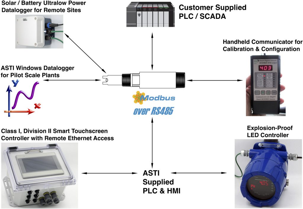
IMPORTANT NOTE: Smart Digital HiQDT sensors are always RS485 MODBUS RTU slaves. Only ONE of the RS485 MODBUS RTU master devices detailed above can be connected at any one time.Core Structure of HiQDT RS485 MODBUS RTU Smart Digital Sensors Installed into Field Service
- Programmable Logic Controller (PLC)
- Human Machine Interface (HMI) can be either local or else available via remote access
- All PLC & HMI functionality shown above is included ASTI touchscreen controllers
- PLC & HMI can be either customer supplied or ASTI provided as desired.
- Windows Software for Setup, Configuration & Calibration of HiQDT sensors
- Search & assign sensor node address & baudrate (HHC can also search and assign node address)
- Configure & calibrate sensors; Save setup to configuration file and produce calibration certificate
- Windows Datalogging & Graphing software records pH, ORP, D.O. ppm & % saturation, ISE ppm, Conductivity μS/cm, Salinity (PSU), TDS and Resistivity (MΩ) and ℃ from connected sensors
- Handheld Communicator (HHC)
- 9V battery powered operation with simple easy to use 4 button operation with bright LED
- Configure and calibrate sensors as well as performing spot measurement on field samples
- Ready for plug & play use right out of the box with zero configuration required
Industrial Internet of Things (IIoT)
The core difference of the HiQDT smart digital sensors is that all user functionality is accessible via the open standard and royalty free RS-485 MODBUS RTU protocol. This is in contrast to the now antiquated sensors and transmitters that only provide a 0-20mA or 4-20mA current loop or 0-5 or 0-10 VDC voltage output containing no diagnostic information whatsoever. The modern HiQDT smart digital sensors take advantage of the industrial internet of things (IIoT) where remote access to all information is available from the sensor in real-time allowing for advanced predictive maintenance and support including remote calibrations and troubleshooting. HiQDT smart digital sensors create an open and collaborative environment for process automation and liquid analytical monitoring enabling a level of connectivity and integration that is not possible with closed architectures such as HART, Profibus, Fieldbus and other proprietary platforms that force vendor lock-in to the client.
Detailed complete documentation is available for the HiQDT smart digital sensors to allow access to all of the user adjustable configuration parameters, analytic data & calibration functions and values as well as sending the engineered temperature compensated process pH & ORP values in very high resolution. Analytics allow for predictive analytics to schedule maintenance in a proactive manner as well as robust monitoring of the process no matter the control system that is currently employed at the given facility. This HiQDT platform gives customers the freedom to interface these sensors with any PLC of their choice so long as it can act as a RS-485 MODBUS RTU master. Support for RS-485 MODBUS RTU master mode on PLC now is very common, if not altogether standard, even for entry level PLC, many of which are also now available with cost-effective remote ethernet access options.
Significance of HiQDT Platform in the Field
The major paradigm shift of the HiQDT smart digital MODBUS sensors and the Industrial Internet of Things (IIoT) means that not only process values can be viewed remotely but ALL functionality that is possible locally standing in front of the HiQDT controller can also be accomplished remotely with robust security and administration for access control. That means fewer trips out in the field to assist clients with commissioning or troubleshooting for any issue that is simply a matter of configuring software or setting controller options.
All of these types of changes can be made remotely with the HiQDT platform building upon the power of the Industrial Internet of Things (IIoT) and accessibility through wired and wireless networks from a Windows PC as well as cellular connected iOS and Android smartphones and tablets. The ability to send email notifications upon any type of trigger event such as reaching a user defined min or max threshold setpoints for the process or temperature reading as well as fault conditions such as loss of communication with sensor mean excellent field maintenance & support even when site is not open to receiving outside visits due to the pandemic.
Typical Field Usage of Smart Digital HiQDT MODBUS RTU Conductivity Sensors
The smart digital HiQDT conductivity sensors with integral MODBUS RTU communications allows for simple & fully portable installation scheme. Sensor may be calibrated anywhere (lab, shop or field) and interfaced with any data acquisition or control system in the field via the RS-485 MODBUS RTU communications. The temperature offset and process value offset calibrations can be done with sensor left in service to agree with a reference value from an external measurement device (please see calibration instructions for details). Waterproof & corrosion-resistant NEMA6P rated HiQ4M snap connector are standard for easy seamless hot-swap of sensors from service for cleaning, recalibration and other maintenance tasks as may be required as well as eventual replacement of sensor in time.
BENEFITS OF SMART DIGITAL HiQDT MODBUS RTU CONDUCTIVITY SENSORS
- Integral RS-485 MODBUS RTU interfaces all-modern PLC controllers & data acquisition systems.
- Communicator provides easy management of field installations without the cost of a mating transmitter. This is ideal for locations where a local display is not necessary or possible due to installation limitations.
- Intelligent management of sensor calibrations and service life-cycle for efficient commissioning & maintenance. All aspects of installation are completely portable from the shop to the field site location.
- Days in use value is stamped for calibrations that are performed. This allows for predictive scheduling of maintenance in the PLC to ensure the accurate measurement in the field based upon user defined criteria.
- All digital sensors ensure reliable operation even in noisy process environments unlike analog sensors.
- No degradation in digital output even with very long cable runs up to max of 1,000 meters (3,280 feet)
- Bridging connections & modifying installations easily without loss of signal quality with NEMA 6P & IP67 rated quick disconnect waterproof and corrosion-resistant dual snap connector. Simple plug and play operation for intelligent maintenance planning & smart management of sensor installations and stocking.
- Low-cost snap digital extension cables facilitate consolidation of very many HiQDT sensors outputs into one panel enclosure where very many remote field installations can all be conveniently all viewed at once.
- Intelligent HiQDT handheld communicator software identifies type of sensor connected & autoloads correct features. There exists no possibility of accidentally using the wrong set of options or settings.
- All Extension cables for HiQDT sensors are inter-compatible. Uniform extension cables minimize stocking. Separate field installation guide details available options to commission & exchange sensors.
SENSORS FOR USE WITH SMART DIGITAL HiQDT WITH RS-485 MODBUS RTU OUTPUT
- Entire line of proven industrial inline, immersion, submersible, sanitary & HOT-TAP valve retractable2-electrode contacting conductivity are ALL availablein the smart digital HiQDT type configuration
- Waterproofing Option “A”, “B”, “C”, “G”, “H” or “IT” recommended for any HiQDT smart digital sensor with integral RS-485 MODBUS RTU digital output when used for fully submersible installations.
SENSORS FOR USE WITH SMART DIGITAL HiQDT WITH RS-485 MODBUS RTU OUTPUT
| Mechanical & Thermal | |
| Housing: | Defined by Conductivity Model & Config |
| Mounting: | Inline, Immersion, Submersible, HOT-TAP & Sanitary as per sensor installation scheme |
| Rating: | Fully submersible and waterproof without use of immersion tube with correct sealing option |
| Connector: | NEMA 6P rated HiQ4M male snap connector for HiQDT snap extension cables; Extension cables for 3TX-HiQ platform can also be used for HiQDT type smart digital sensors as well |
| Max Cable: | Up to 3,280 feet (1,000 meters) using 22 AWG leads when employing 12VDC power supply |
| Temp.: | Inline max per sensor specs; Submersible Use limited to Max 85℃ for all sensor models |
| Pressure: | Up to 500 psig inline use for selected models |
| Weight: | Varies depending upon sensor type & config |
| Dimensions: | Minimum size is ½ ” MNPT for inline installations with AST10/AST51 Sensors; Minimum size is ¾” MNPT for HOT-TAP Valve Retractable Installations; Minimum size is ¾” TRI-CLOVER for |
| Electrical | |
| Operating VDC: | 8.0 to 13.0 VDC at sensor board |
| Power Supply: | Isolated & Regulated 9V or 12V DC |
| Current draw: | Max 35mA Absolute, Typical ~30mA |
| Conductivity Ranges: | See Tables for Available Range Modes for each Cell Constant |
| Temp Sensor: | Integral Platinum 1000Ω TC Element |
| Temp Range: | -40 to +210℃ ±0.3℃ (limited by actual sensor specifications) Max Temp is +85℃ at sensor board (submersible) |
| Temp. Comp.: | Automatic for all measurements |
| Digital Output: | Isolated RS-485 MODBUS RTU |
| Baud rate: | 9600 or 19,200 kbps (selectable) |
| Compatibility: | ASTI Handheld Communicator (HHC) or Windows HiQDT software or any PLC with isolated RS-485 input that can serve as a MODBUS RTU master to HiQDT sensor slave |
| CE mark: | EN61326A |
STANDARD RANGE MODE * – in microSiemens/cm
| Range Scaling Factor | 200 | Max Temp. Compensated Conductivity using 2% per ℃ Coefficient | ||||
|---|---|---|---|---|---|---|
| Cell Constant (K) | Max Raw Input Limit | Resolution | Lowest Recommended Measurement @ 25℃ | @ 25℃ | @ 75℃ | @ 125℃ |
| 0.01 | 200 | 0.004 | 2 | 200 | 100 | 66.67 |
| 0.02 | 400 | 0.008 | 4 | 400 | 200 | 133.33 |
| 0.05 | 1,000 | 0.02 | 10 | 1,000 | 500 | 333.33 |
| 0.10 | 2,000 | 0.04 | 20 | 2,000 | 1,000 | 666.67 |
| 0.20 | 4,000 | 0.08 | 40 | 4,000 | 2,000 | 1,333.33 |
| 0.50 | 10,000 | 0.2 | 100 | 10,000 | 5,000 | 3,333.33 |
| 1.00 | 20,000 | 0.4 | 200 | 20,000 | 10,000 | 6,666.67 |
| 2.00 | 40,000 | 0.8 | 400 | 40,000 | 20,000 | 13,333.33 |
| 3.00 | 60,000 | 1.2 | 600 | 60,000 | 30,000 | 20,000.00 |
| 5.00 | 100,000 | 2 | 1,000 | 100,000 | 50,000 | 33,333.33 |
| 10.00 | 200,000 | 4 | 2,000 | 200,000 | 100,000 | 66,666.67 |
| 20.00 | 400,000 | 8 | 4,000 | 400,000 | 200,000 | 133,333.33 |
HIGH RANGE MODE * – in microSiemens/cm
| Range Scaling Factor | 2000 | Max Temp. Compensated Conductivity using 2% per ℃ Coefficient | ||||
|---|---|---|---|---|---|---|
| Cell Constant (K) | Max Raw Input Limit | Resolution | Lowest Recommended Measurement @ 25℃ | @ 25℃ to to 75℃ | @ 125℃ | @ 175℃ |
| 0.01 | 2,000 | 0.04 | 20 | 1,000 | 666.67 | 500 |
| 0.02 | 4,000 | 0.08 | 40 | 2,000 | 1,333.33 | 1,000 |
| 0.05 | 10,000 | 0.2 | 100 | 5,000 | 3,333.33 | 2,500 |
| 0.10 | 20,000 | 0.4 | 200 | 10,000 | 6,666.67 | 5,000 |
| 0.2 | 40,000 | 0.8 | 400 | 20,000 | 13,333.33 | 10,000 |
| 0.5 | 100,000 | 2 | 1,000 | 50,000 | 33,333.33 | 25,000 |
| 1.00 | 200,000 | 40 | 2,000 | 100,000 | 66,666.67 | 50,000 |
| 2.00 | 400,000 | 8 | 4,000 | 200,000 | 133,333.33 | 100,000 |
| 3.00 | 600,000 | 12 | 6000 | 300,000 | 200,000.00 | 150,000 |
| 5.00 | 1,000,000 | 20 | 10,000 | 500,000 | 333,333.33 | 250,000 |
| 10.00 | 2,000,000 | 40 | 20,000 | 1,000,000 | 666,666.67 | 500,000 |
| 20.00 | 4,000,000 | 80 | 40,000 | 2,000,000 | 1,333,333.33 | 1,000,000 |
* Sensor can toggle between standard/high range mode range mode while in use. Standard/high range mode sensor is one configuration and associated sensor board hardware. Ultralow range mode sensor is a different configuration and associated sensor board. While you can toggle between standard and high range modes you cannot toggle between the standard/high and ultralow modes since these are two different sensor boards. Two slope calibrations are stored in dual mode standard/high sensors; slope low is used for the standard mode and slope high for the high mode. Slope calibrations are automatically assigned based upon range mode in use for sensor at time when calibration is performed. The ultralow range mode only uses the single low slope (slope high is unused).
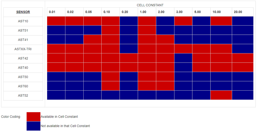
All sensors are available in smart digital HiQDT MODBUS RTU configuration although not all cell constants are available for each model. Use the standard & high range mode cell constant table above & ultralow range mode table below to determine most suitable selection for your sample. Cell constants above K=2.00/cm omitted from ultralow range table but available on request.
ULTRA-LOW RANGE MODE in microSiemens/cm
| Range Scaling Factor | 2 | Max Temp. Compensated Conductivity using 2% per ℃ Coefficient | ||||
|---|---|---|---|---|---|---|
| Cell Constant (K) | Max Raw Input Limit | Resolution | Lowest Recommended Measurement @ 25℃ | @ 25℃ | @ 75℃ | @ 125℃ |
| 0.01 | 2 | 0.00004 | 0.02 | 2 | 1 | 0.667 |
| 0.02 | 4 | 0.00008 | 0.04 | 4 | 2 | 1.333 |
| 0.05 | 10 | 0.0002 | 0.1 | 10 | 5 | 3.333 |
| 0.10 | 20 | 0.0004 | 0.2 | 20 | 10 | 6.667 |
| 0.20 | 40 | 0.0008 | 0.4 | 40 | 20 | 13.333 |
| 0.50 | 100 | 0.002 | 1.0 | 100 | 50 | 33.333 |
| 1.00 | 200 | 0.004 | 2.0 | 200 | 100 | 66.667 |
| 2.00 | 400 | 0.008 | 4.0 | 400 | 200 | 133.33 |
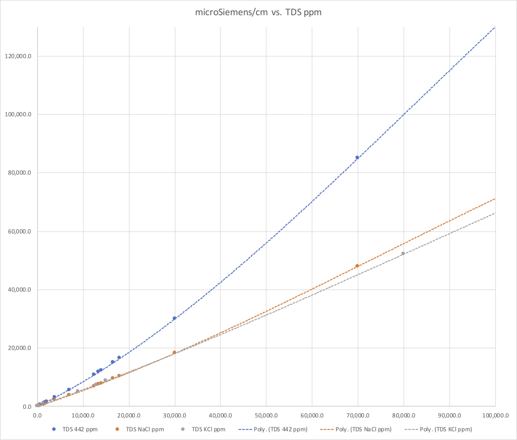
Total dissolved solids (TDS) units are computed from measured conductivity. The curves that define relationship between the measured conductivity and user selectable total dissolved solid (TDS) units of NaCl, KCl or 442 are preprogrammed into sensor with full range of 0 to 100,000 ppm. The actual usable range may be limited by the choice of cell constant and range mode in which the sensor is operated.
Other types of total dissolved solids (TDS) for other electrolytes or electrolyte mixtures can be programmed into the sensor on a special-order basis (minimum order requirements apply for such special programming requests). Inquire to the factory if you have need for such special TDS units for your smart digital HiQDT MODBUS RTU conductivity sensors.
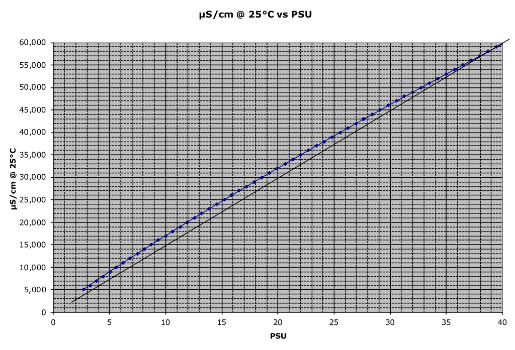
Salinity computed from the measured conductivity. Curves that define the relationship between measured conductivity and the computed salinity in PSU are preprogrammed into the sensor with a full range of 0.000 to 50.000 PSU.
The actual supported range may be limited by cell constant & range mode used). Contact the factory to determine the most suitable sensor model and cell constant configuration for your desired salinity range of interest.
Ultralow Range Conductivity Sensors for Ultrapure Water (UPW)
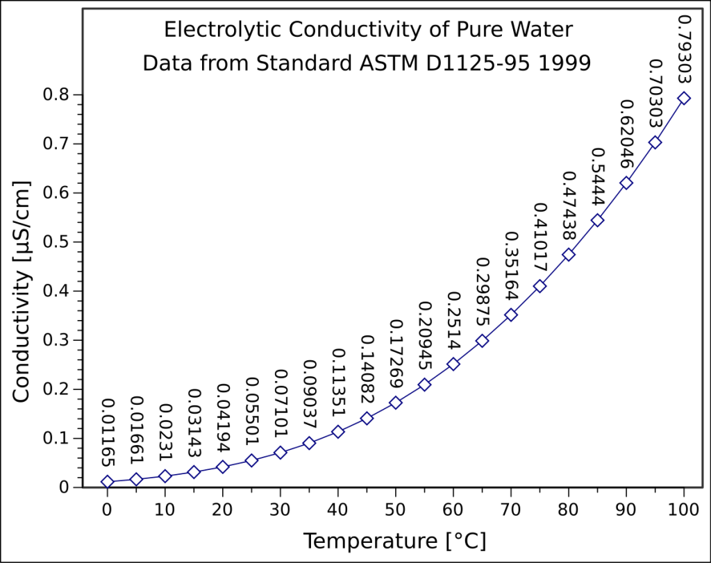
The conductivity of pure water varies significantly with temperature in a well-defined but non-linear fashion as detailed in the graph to left. This behavior is preprogrammed into the HiQDT-CON-L MODBUS RTU conductivity sensors for the automatic temperature compensation feature to make it suitable for ultrapure water (UPW) type applications.
Although the recommended cell constant for performing conductivity measurement in UPW is K=0.01/cm for best resolution and lower bounds of measurement there may be situations where this K=0.01/cm cell constant cannot be used for the planned installation location because of limitations such as piping arrangement and low-flow. The higher cell constants of K=0.05/cm or K=0.10/cm can be used instead in such cases albeit they require the sample to be at a higher temperature to ensure best results. Table below details recommended minimum temperature for various cell constants for use in UPW. The minimum temperature for UPW measurement for each cell is determined based upon the lowest absolute conductivity value for which the cell constant is recommended & temperature at which this conductivity occurs for UPW. Resistivity are computed units are the inverse of the measured conductivity value.
ULTRA-LOW RANGE MODE – MicroSiemens/cm
| Range Scaling Factor | 2 | ||||
|---|---|---|---|---|---|
| Cell Constant (K) | Raw Max Input @ 25℃ | Resolution | Lowest Recommended Absolute Measurement | Minimum Temp ℃ * | Absolute MegaOhm (MΩ) @ Min Recommended ℃ * |
| 0.01 | 2 | 0.00004 | 0.02 | 8 | 50 |
| 0.05 | 10 | 0.0002 | 0.1 | 40 | 10 |
| 0.10 | 20 | 0.0004 | 0.2 | 55 | 5 |
* Minimum recommended temperature is conductivity of UPW which is 1% of ultralow range mode for the given cell and the associated MegaOhm units. Measurements can be performed below the recommended minimum temperature with an associated higher uncertainty for those situations.
For ultralow range conductivity sensors the 5th read input register (30005) sends the computed resistivity MegaOhm (MΩ) using the user defined linear automatic temperature compensation (ATC) while the 6th read input register (30006) sends computed resistivity MegaOhm (MΩ) using the special non-linear ultrapure water style automatic temperature compensation. The resistivity values sent as 0 to 50,000 steps corresponding to 0.000-50.000 MegaOhm (MΩ) for both the 5th (30005) & 6th (30006) read input registers. Theoretical temperature compensated resistivity value can never go above 18.18 MegaOhm (MΩ) for uncontaminated pure water since this is the ideal value at 25 degrees Celsius.
Temperature compensated conductivity and resistivity are referenced back to the 25 ℃ condition for all ATC. Ultrapure water with no contaminants has a value of 0.055 μS/cm conductivity or 18.18 MΩ in resistivity. The most common units for measurement of pure water is resistivity (MΩ) MegaOhm due to high resolution and convenient scaling in the very low conductivity levels. Temperature compensated conductivity and computed resistivity values sent for the ultralow range mode smart digital HiQDT-CON-UL style MODBUS RTU conductivity sensors as well as the raw conductivity.
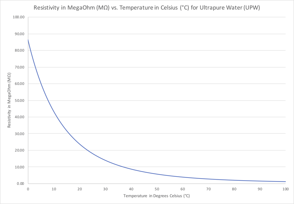
Graph above shows relationship between the resistivity of pure water at various temperatures. Computed resistivity MegaOhm (MΩ) units are the inverse of measured conductivity and so are the mirror image of the conductivity at various temperatures for ultrapure water (UPW). Graph above shows absolute raw resistivity at various temperatures. Resistivity values sent include ATC referencing reading to 25 ℃ state.
HiQDT-CON-ISO-L-10X SENSOR CELL & RANGE TABLE FOR ULTRALOW-10X HARDWARE
ULTRA-LOW RANGE MODE 10X * in microSiemens/cm
| Range Scaling Factor | 2 | Max Temp. Compensated Conductivity using 2% per ℃ Coefficient | |||||
|---|---|---|---|---|---|---|---|
| Nominal Cell Int ** | ACTUAL Cell Constant | Max Raw Input Limit | Resolution *** | Lowest Recommended Measurement @ 25℃ | @ 25℃ | @ 75℃ | @ 125℃ |
| 10 | 0.01 | 20 | 0.0004 | 0.2 | 20 | 10 | 6.667 |
| 20 | 0.02 | 40 | 0.0008 | 0.4 | 40 | 20 | 13.333 |
| 50 | 0.05 | 100 | 0.002 | 1.0 | 100 | 50 | 33.333 |
| 100 | 0.1 | 200 | 0.004 | 2.0 | 200 | 100 | 66.667 |
| 200 | 0.2 | 400 | 0.008 | 4.0 | 400 | 200 | 133.33 |
| 500 | 0.5 | 1,000 | 0.02 | 10.0 | 1,000 | 500 | 333.333 |
| 1000 | 1.0 | 2,000 | 0.04 | 20 | 2,000 | 1,000 | 666.67 |
| 2000 | 2.0 | 4,000 | 0.08 | 40 | 4,000 | 2.000 | 1,333.33 |
* Range mode defined by register 40018. When register 40018 is 2 then range scaling factor is ultralow mode. This register 40018 is read only for the ultralow mode sensor type.
** The nominal cell constant of conductivity sensor is found by dividing integer obtained from register 40019 by 100.
*** The resolution is always 50,000 steps no matter the nominal cell constant of sensor or range mode that is in operation.
If sensor used is only ever just one cell constant and range mode, then simple scaling of 0-50,000 steps to conductivity range is possible. Procedure below supports any cell constant in any range mode without changing programming of MODBUS RTU master PLC device:
1) Converting registers 30001 & 30003 for conductivity sensors into μS/cm conductivity units
To display calibrated & temperature compensated conductivity in μS/cm units, use the following formula:
uS/cm = ( ( REG30001 * REG40019 ) * REG40018 ) / 50,000
To display calibrated raw conductivity in μS/cm units use register 30003 instead of 30001 in formula above.
2) Converting μS/cm conductivity units into native 0-50,000 step sensor resolution units
When performing the autocalibration calls on the conductivity sensor you will need to convert from the engineered μS/cm conductivity units to the 0 to 50,000 native resolution units of the conductivity sensor using this formula:
Native 0-50,000 sensor resolution units = ( uS/cm * 50,000 ) / ( REG40019 * REG40018 )
Native 0-50,000 sensor resolution units are what is sent to register 40011 (ultralow slope).
SPECIAL NOTES ABOUT ULTRALOW-10X STYLE SPECIAL ORDER SENSORS:
It is not possible to tell whether the sensor that you have is the Ultralow style or the Ultralow-10X style simply from looking at register 40018 since this would be 2 in both cases. The only way to tell that you have the Ultralow-10X style hardware is that the nominal cell constant detailed in register 40019 will be 10 times higher than the actual cell constant as indicated on the sensor label. This ten-fold deviation between the nominal and the actual cell constant is what is to be expected if you have purchased the Ultralow-10X style sensor. The range of the Ultralow-10X follows what would be expected if the actual cell constant was ten times higher for the same ultralow sensor configuration. Contact factory if you should have any questions or concerns prior to ordering.
AST50 & AST60 Smart MODBUS RTU Conductivity Sensors
Wetted Materials of Construction
- Insulator
- CPVC (AST50) or TEFLON (AST60)
- O-Rings
- EPDM (Std); Viton, AFLAS or KALREZ
- Electrodes
- 316SS (Std); Titanium, Monel, Hast C-276
Sensor Body
-
- CPVC (AST50) or KYNAR (AST60)
Cell Constants
-
- From K = 0.1/cm up to K = 2.0/cm
Measurement Ranges
- Standard * Download Specification Sheet
- From 2 to 400,000 μS/cm
- High * Download Specification Sheet
- From 20 to 2,000,000 μS/cm
- Ultralow * Download Specification Sheet
- From 0.02 to 4,000.00 μS/cm
- From 0.00025 to 50.000 MΩ
Temperature Limits
- -35 to +95 ℃ (-31 to +203 ℉) for AST50
- -35 to +120 ℃ (-31 to +248 ℉) for AST60
- -35 to +85 ℃ (-31 to +185 ℉) for fully submersible use
Pressure Limits
- Max 100 psig @ 95℃ for AST50
- Max 100 psig @ 120℃ for AST60
Installation Styles Supported
- Inline, Immersion or Submersible
- Waterproofing sealing option recommended for submersible installations without immersion rod
Typical Applications
- Water quality & wastewater treatment monitoring
- Mixed use portable & continuous field measurements
Special Features
- Open geometry is a good choice for samples with high viscosity and/or particulars that may tend to foul as well as low-flow type installations to avoid entrapped air bubbles in field use with varying flow & pressure
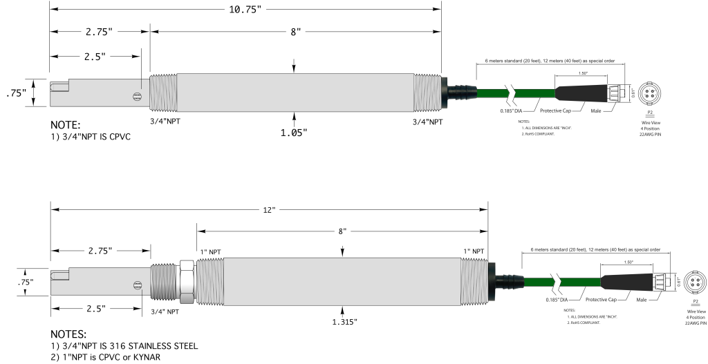
AST42 Smart Digital MODBUS RTU Conductivity Sensors
Wetted Materials of Construction
- Insulator
- PEEK
- O-Rings
- EPDM (Std); Viton, AFLAS or KALREZ
- Electrodes
- 316SS (Std); Titanium, Monel, Hast C-276
Sensor Body
- CPVC or KYNAR
Cell Constants
- From K = 0.01/cm up to K = 20.0/cm
Measurement Ranges
- Standard * Download Specification Sheet
- From 2 to 400,000 μS/cm
- High * Download Specification Sheet
- From 20 to 2,000,000 μS/cm
- Ultralow * Download Specification Sheet
- From 0.02 to 4,000.00 μS/cm
- From 0.00025 to 50.000 MΩ
Temperature Limits
- -35 to +205 ℃ (-31 to +401 ℉) for inline installations
- -35 to +85 ℃ (-31 to +185 ℉) for fully submersible use
Pressure Limits
For Installations WITH Compression Fitting
- Max 100 psig @ 100℃ with polypropyelene (PP)
- Max 400 psig @ 100℃ or 250 psig @ 205℃ with 316SS
For Installations WITHOUT Compression Fitting
- Max 100 psig @ 95℃ for CPVC Sensor Body
- Max 100 psig @ 120℃ for KYNAR Sensor Body
Installation Styles Supported
- Inline, Immersion or Submersible
- Waterproofing sealing option recommended for submersible installations without immersion rod
Typical Applications
- High temperature and/or high pressure installation where a low or high cell constant is needed for range
- Installs where special materials of construction required
Special Features
- Variable insertion depth with compression fitting option
AST40 Smart Digital MODBUS RTU Conductivity Sensors for HOT-TAP Valve Retractable Field Installations
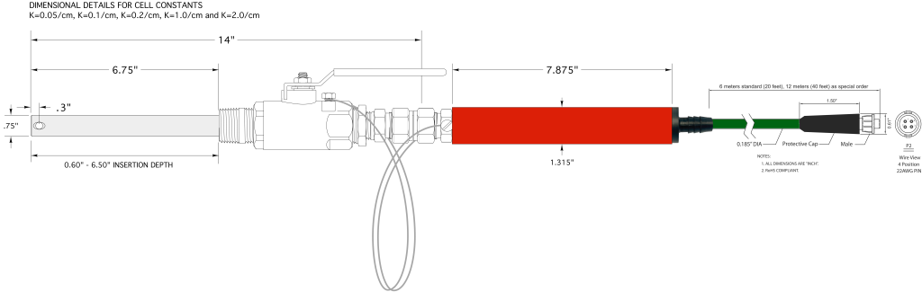
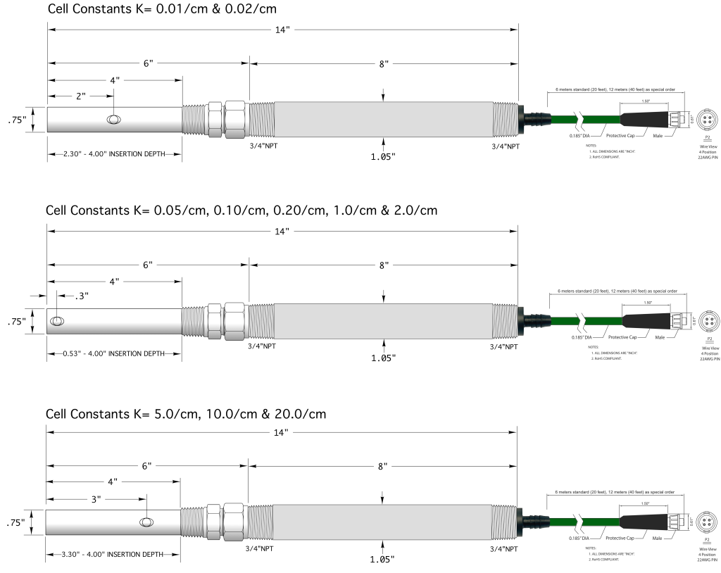
Drawing valid for K= 0.05, 0.10, 0.20, 0.50, 1.0 & 2.0 /cm cells. Position of vent hole & associated insertion depth differs for low cells of K= 0.01 & 0.02 /cm & high cells K= 5.0, 10.0 & 20.0 /cm. Inquire to factory for drawings of these alternate cell constants. Smaller valve retractable configuration employing ¾”MNPT full port ball valve with ½”O.D. sensor available upon request.
Wetted Materials of Construction
- Insulator
- PEEK or TEFLON
- O-Rings
- EPDM (Std); Viton, AFLAS or KALREZ
- Electrodes & Ball Valve
- 316SS (Inquire to factory for other options)
Sensor Body
- CPVC or KYNAR
Cell Constants
- From K = 0.01/cm up to K = 20.0/cm
Measurement Ranges
- Standard * Download Specification Sheet
- From 2 to 400,000 μS/cm
- High * Download Specification Sheet
- From 20 to 2,000,000 μS/cm
- Ultralow * Download Specification Sheet
- From 0.02 to 4,000.00 μS/cm
- From 0.00025 to 50.000 MΩ
Temperature Limits
- -35 to +205 ℃ (-31 to +401 ℉) for inline installations
Pressure Limits
- Max 400 psig @ 100℃ or 250 psig @ 205℃ when the sensor is stationary with compression fitting tightened
- Up to Max 150 psig while sensor is being either inserted or removed from field service
- Min 50 psig under all process conditions and installs
Typical Applications
- High temperature and/or high pressure installation where a low or high cell constant is needed for range
- Installs where sensor must be inserted and removed without shutting down process and where slip-stream installation scheme is not possible to implement
Special Features
- Variable insertion depth for HOT-TAP valve retractable installations without shutting down process stream
* Sensor can toggle between standard & high range mode in field.
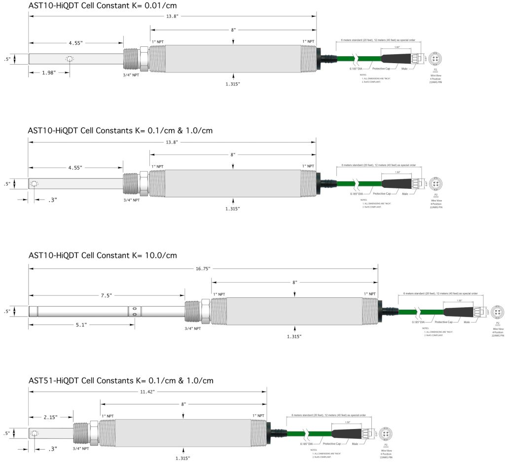
AST10 & AST51 Smart MODBUS RTU Conductivity Sensors
Wetted Materials of Construction
- Insulator
- TEFLON (PTFE)
- O-Rings
- EPDM (Std); Viton, AFLAS or KALREZ
- Electrodes
- 316SS (Std); Titanium, Monel, Hast C-276
Sensor Body
- CPVC or KYNAR
Cell Constants
- From K = 0.01/cm up to K = 10.0/cm
Measurement Ranges
- Standard * Download Standard/Hi Range Spec Sheet
- 0.02-2, 0.04-4, 0.2-20, 0.4-40 mS/cm
- High * Download Standard/Hi Range Spec Sheet
- 0.2-10, 0.4-20, 2-100, 4-200 mS/cm
- Ultralow * Download Standard/Hi Range Spec Sheet
- 0.2-20, 2.0-200, 4.0-400 μS/cm
- 0.050-5.000, 0.005-0.500, 0.0025-0.250 MΩ
Temperature Limits
- -35 to +100 ℃ (-31 to +212 ℉) inline Polypropylene (PP)
- -35 to +120 ℃ (-31 to +248 ℉) inline KYNAR or 316SS
- -35 to +85 ℃ (-31 to +185 ℉) for fully submersible use
Pressure Limits
For Installations WITH Compression Fitting
- Max 100 psig @ 100℃ with Polypropyelene (PP)
- Max 150 psig @ 120℃ with KYNAR (PVDF)
- Max 500 psig @ 100℃ or 200 psig @ 120℃ with 316SS
For Installations WITHOUT Compression Fitting
- Max 100 psig @ 95℃ for CPVC Sensor Body
- Max 100 psig @ 120℃ for KYNAR Sensor Body
Installation Styles Supported
- Inline, Immersion or Submersible
Typical Applications
- ½” Inline installations where compact footprint needed
Special Features
- Variable insertion depth with compression fitting option
Sanitary Smart Digital MODBUS RTU Conductivity Sensors

Wetted Materials of Construction
- Insulator
- CPVC (AST50) or TEFLON (AST60)
- O-Rings
- EPDM (Std); Viton or Kalrez
- Electrodes
- 316SS (Std); Titanium, Monel, Hast C-276
Sensor Body
- CPVC (AST50) or KYNAR (AST60)
Cell Constants
- From K = 0.01/cm up to K = 10.0/cm
Measurement Ranges
- Standard * Download Specification Sheet
- From 2 to 200,000 μS/cm
- High * Download Specification Sheet
- From 20 to 1,000,000 μS/cm
- Ultralow * Download Specification Sheet
- From 0.02 to 2,000.00 μS/cm
- From 0.0005 to 50.000 MΩ
Temperature Limits
- -35 to +130 ℃ (-31 to +266 ℉) TEFLON (PTFE) Insulator
- -35 to +205 ℃ (-31 to +401 ℉) PEEK Insulator
Pressure Limits
- Max 150 psig @ 130℃ or 500 psig @ 25℃
- Rating for TEFLON (PTFE) Insulator
- Max 250 psig @ 205℃ or 500 psig @ 100℃
- Rating for PEEK Insulator
Installation Styles Supported
- Sanitary TRI-CLOVER or Ladish Flange
- Sizes from from ¾” up to 2½” available
- Max 100 psig @ 120℃ for KYNAR Sensor Body
Typical Applications
- Food, Dairy, Beverage and Pharmaceutical Industries
- Monitoring and control of both steam in place (SIP) and chemical clean in place (CIP) processes for sterilization
Special Features
- Quick disconnect for high pressure inline installations where fouling may occur means ease of removal from process for cleaning without coiling sensor cable
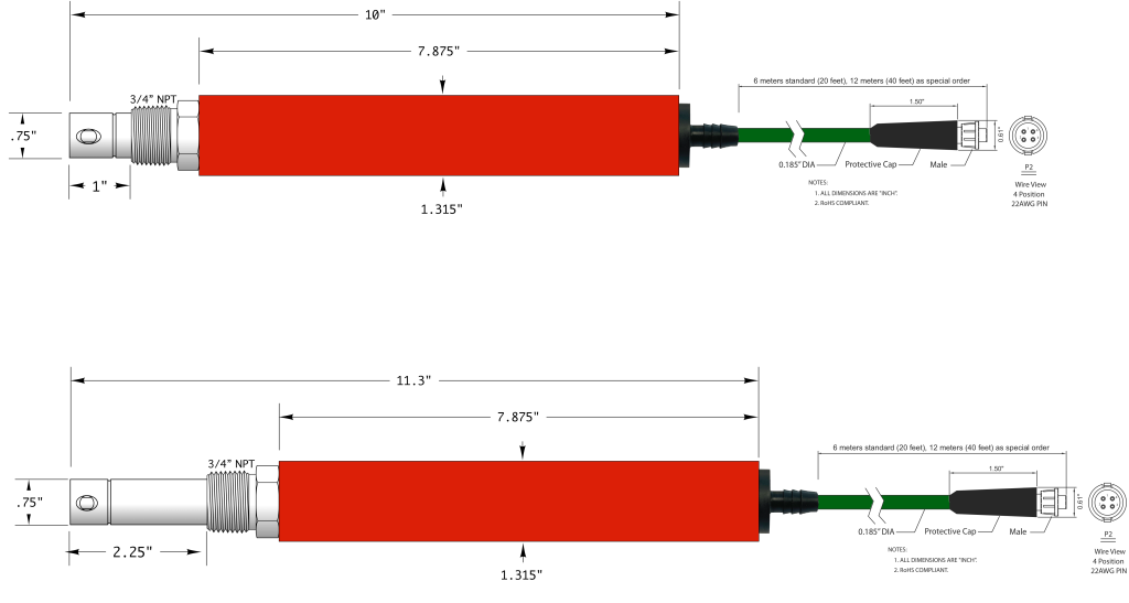
AST41 Smart Digital MODBUS RTU Conductivity Sensors
Wetted Materials of Construction
- Insulator
- PEEK
- O-Rings
- EPDM (Std); Viton, AFLAS or KALREZ
- Electrodes
- 316SS
Sensor Body
- CPVC or KYNAR
Cell Constants
- K = 0.05, 0.1, 0.2, 1.0 or 2.0 /cm
Measurement Ranges
- Standard * Download Specification Sheet
- 10-1,000 (K=0.05), 20-2,000 (K=0.1), 40-4,000 (K=0.2), 200-20,000 (K=1.0), 400-40,000 (K=2.0)
- Units indicated above are μS/cm
- 10-1,000 (K=0.05), 20-2,000 (K=0.1), 40-4,000 (K=0.2), 200-20,000 (K=1.0), 400-40,000 (K=2.0)
- High * Download Specification Sheet
- 100-5,000 (K=0.05), 200-10,000 (K=0.1), 400-20,000 (K=0.2), 2,000-100,000 (K=1.0), 4,000-200,000 (K=2.0)
- Units indicated above are μS/cm
- 100-5,000 (K=0.05), 200-10,000 (K=0.1), 400-20,000 (K=0.2), 2,000-100,000 (K=1.0), 4,000-200,000 (K=2.0)
- Ultralow * Download Specification Sheet
- 0.1-10 (K=0.05), 0.2-20 (K=0.1), 0.4-40 (K=0.2), 2.0-200 (K=1.0), 4.0-400 (K=2.0),
- Units indicated above are μS/cm
- 0.1-10 (K=0.05), 0.05-5 (K=0.1), 0.025-2.5 (K=0.2), 0.005-0.500 (K=2.0), 0.0025-0.25 (K=2.0),
- Units indicated above are MΩ
- 0.1-10 (K=0.05), 0.2-20 (K=0.1), 0.4-40 (K=0.2), 2.0-200 (K=1.0), 4.0-400 (K=2.0),
Temperature Limits
- -35 to +205 ℃ (-31 to +401 ℉)
- -35 to +85 ℃ (-31 to +185 ℉) for fully submersible use
Pressure Limits
- Max 500 psig @ 100℃ or 250 psig @ 205℃
- Rating for inline use with front 316SS Threads
- Max 250 psig @ 205℃ or 500 psig @ 100℃
- Rating for PEEK Insulator
Installation Styles Supported
- Inline Only
- Waterproofing sealing option recommended for submersible installations without immersion rod
- Max 100 psig @ 120℃ for KYNAR Sensor Body
Typical Applications
- Blowdown control, condensate monitoring & leak detection on heat exchangers & high purity steam
- Boiler condensate and blowdown control and/or monitoring in installation locations without coolers
- High pressure & temperature conductivity measurements applications such as high-pressure desalination and reverse osmosis (RO) reject concentrate monitoring and control
- High temperature and pressure water and steam in any severe service type environment
Special Features
- Available in either standard 1.0 inch or extended 2.25 inch insertion depths as most ideal for installation
- Ultra-rugged construction allows for long service lifetime in the most aggressive field use scenarios
AST52 Smart Digital MODBUS RTU Conductivity Sensors
Wetted Materials of Construction
- Insulator
- CPVC (Std); TEFLON or PEEK Special Order
- O-Rings
- EPDM (Std); Viton, AFLAS or KALREZ
- Electrodes
- 316SS (Std); Titanium, Monel, Hast C-276
Front Sensor Body (Wetted)
- CPVC or 316SS
Rear Sensor Body (Non-Wetted)
- CPVC or KYNAR (PVDF)
Cell Constants
- K = 10.0/cm
Measurement Ranges
- Standard * Download Specification Sheet
- 2,000-200,000 μS/cm (2-200 mS/cm)
- High * Download Specification Sheet
- 20,000-1,000,000 μS/cm (20-1,000 mS/cm)
Temperature Limits
- -35 to +95 ℃ (-31 to +203 ℉) with CPVC insulator
- -35 to +120 ℃ (-31 to +248 ℉) with TEFLON insulator
- -35 to +150 ℃ (-31 to +302 ℉) with PEEK insulator
- -35 to +85 ℃ (-31 to +185 ℉) for fully submersible use
Pressure Limits
For Installations with CPVC Sensor Body
- Max 80 psig @ 95℃ with CPVC Insulator
For Installations with 316SS Sensor Body
- Max 100 psig @ 95℃ or Max 500 psig @ 50℃
- Rating for CPVC Insulator
- Max 100 psig @ 120℃ or Max 500 psig @ 80℃
- Rating for TEFLON (PTFE) Insulator
- Max 100 psig @ 150℃ or Max 500 psig @ 100℃
- Rating for {EEL Insulator
Installation Styles Supported
- Inline, Immersion or Submersible
- Waterproofing sealing option recommended for submersible installations without immersion rod
Typical Applications
- Saturated brines, brackish water and seawater
- High concentration electrolytes, acids and bases
Special Features
- Very compact insertion depth for inline installations with very high conductivity
- Cost effective solution when exotic materials of construction are required for measuring electrodes